

Short answer: The most common injection moulding defects are flash, short shots, sink marks, burn marks, flow marks, weld lines, warping, voids, jetting, splay (silver streaks) and delamination. Most come from process settings (temperature, pressure, speed, cooling time); the rest need a change to the part or mould design, such as even wall thickness, gate position or venting.
Injection molding presents a considerable risk of costly errors. From minor surface imperfections to more severe issues impacting safety and functionality, the spectrum of quality problems is wide-ranging.
Let's delve into the primary quality defects associated with injection molding, their causative factors, and preventive measures.
MOLDING DEFECTS ATTRIBUTED TO PROCESS IRREGULARITIES
While some molding defects pose significant challenges in rectification, others can be forestalled by refining the molding process. Adjustments in flow rate, temperature, or pressure within the mold can often circumvent these defects without necessitating mold tooling redesign or equipment replacement. Hence, with relatively simple adjustments, these defects can typically be sidestepped.
Outlined below are common defects stemming from manufacturing process errors:
1. Flash
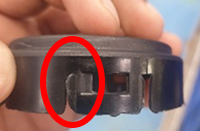 Flash is a thin, unwanted layer of plastic that escapes from the mould cavity and solidifies along the parting line, around ejector pins or at vents. It is usually easy to see as a sharp fin or lip on the edge of the part. Small flash can be trimmed, but it adds labour, can affect fit and assembly, and is a sign that the mould or process needs attention.
Causes of Flash
Flash forms when the molten plastic finds a gap it can flow into. Typical causes are a clamp force too low for the projected area of the part, injection pressure or speed set too high, melt temperature too high (which makes the plastic very fluid), vents cut too deep, and worn or damaged parting surfaces that no longer close tightly.
Remedies for Flash- i. Use enough clamp force
Run the mould on a machine whose clamp tonnage suits the part's projected area, so the mould halves stay closed during injection.
- ii. Adjust the process
Reduce injection pressure, speed or hold pressure, and lower the melt temperature to the material supplier's recommended range.
- iii. Maintain the mould
Clean and repair parting surfaces, check that vents are the right depth for the material, and keep ejector pins and their holes within tolerance.
2. Short shot
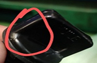
A "short shot" arises when molten material fails to completely occupy the voids within a mold. Consequently, the resultant molded component remains unfinished post-cooling. Instances of short shots may manifest as incompletely formed sections in plastic display shelves or as absent prongs on a plastic fork, among other examples. Generally, short shots are deemed significant defects capable of impeding both the functionality and aesthetics of the molded part.
Causes and Solutions for Short Shots in Molded Products
The primary cause of short shots typically stems from flow restriction, often due to narrow or obstructed gates. At times, the material's viscosity may be excessive, or the mold's temperature too low, preventing complete filling before cooling occurs. Additionally, trapped air pockets or insufficient injection pressure can also impede proper flow. To mitigate short shot occurrences, consider the following measures:
- i. Redesign the mold to incorporate wider channels or gates, facilitating smoother material flow.
- ii. Enhance injection speed or pressure, or opt for a thinner base material to enhance flow dynamics.
- iii. Elevate mold temperature to mitigate rapid cooling of the material.
- iv. Introduce additional air vents or expand existing ones within the mold to facilitate the release of trapped air.
3. Sink Marks
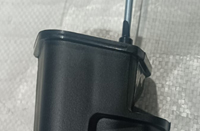
Sink marks refer to small recesses or depressions that appear on an otherwise flat and uniform surface of a molded part. These imperfections occur when the inner section of a molded component contracts during cooling, causing material to be drawn inward from the outer layers.
Understanding the Causes and Prevention of Sink Marks:
Sink marks share similarities with vacuum voids but differ in their underlying cause and effect. In the case of sink marks on a plastic injection molded part, rather than material cooling too rapidly near the part's exterior, it cools too slowly. Consequently, the material contracts unevenly, pulling the outer layers inward prematurely before sufficient cooling has occurred, resulting in depressions.
To effectively prevent sink marks, several measures can be implemented:- i. Increase holding pressure and extend the holding time to facilitate adequate cooling of the material near the part's surface.
- ii. Extend the cooling time to minimize shrinkage during the cooling process.
- iii. Optimize the mold design by incorporating thinner walls for the components, allowing for faster cooling near the surface.
4. Burn marks
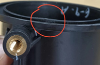
Burn marks typically manifest as dark or rust-colored discolorations on the edges or surfaces of molded plastic components. These marks usually do not compromise the integrity of the part unless the plastic has been significantly degraded by the burning process.
Understanding the Causes and Prevention of Burn Marks:
Trapped air or resin overheating within the mold cavity during the injection process are frequently the main causes of burn marks in injection-molded parts. High injection speeds or excessive heating of the material can exacerbate this issue, leading to overheating and subsequent burns. To mitigate the occurrence of burn marks, consider implementing the following preventive measures:
- i. Lowering the melt and mold temperatures to prevent overheating.
- ii. Reducing the injection speed to minimize the risk of air entrapment within the mold.
- iii. Enlarging gas vents and gates to facilitate the escape of trapped air from the mold.
- iv. Shortening the mold cycle time to prevent prolonged exposure of trapped air and resin to high temperatures, thereby averting overheating issues.
5. Flow marks
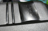
In injection molding, flow marks, also known as flow lines, occur when the molten plastic material cools and solidifies at different rates as it flows through the mold cavity. This can result in visible lines or marks on the surface of the molded part, which can affect its aesthetics and sometimes its mechanical properties. Flow marks are typically more noticeable in transparent or translucent parts.
Causes of flow marks in injection molding:
i. Injection Speed: High injection speeds can lead to turbulence in the molten plastic, causing flow marks as the material cools unevenly.
ii. Melt Temperature: If the melt temperature is too low, the material may solidify too quickly, resulting in flow marks.
iii. Mold Temperature: Improper mold temperature control can cause variations in cooling rates, leading to flow marks.
iv. Material Selection: Certain materials are more prone to flow marks than others, especially those with high viscosity or poor flow properties.
v. Gate Design: Improper gate design or location can cause flow marks by directing the flow of molten plastic in a way that creates uneven cooling.
Remedies for flow marks in injection molding:
i. Adjust Injection Speed: Lowering the injection speed can reduce turbulence and improve the flow of the molten plastic, reducing the likelihood of flow marks.
ii. Optimize Melt Temperature: Ensure that the melt temperature is within the recommended range for the material being used. Increasing the melt temperature can help improve flow and reduce flow marks.
iii. Control Mold Temperature: Properly control the mold temperature to ensure uniform cooling throughout the part. This may involve adjusting coolant flow rates or using mold temperature controllers.
iv. Material Selection: Choose a material with better flow properties or additives specifically designed to minimize flow marks.
v. Gate Design: Optimize gate design and location to promote smoother flow of molten plastic into the mold cavity, reducing the likelihood of flow marks.
vi. Venting: Ensure proper venting in the mold to allow air and gases to escape, preventing pressure buildup that can cause flow marks.
vii. Injection Pressure:Adjusting injection pressure can help in controlling the flow of the molten plastic and reducing flow marks.
viii. Mold Surface Finish:A polished mold surface finish can help minimize flow marks by promoting smoother flow of the molten plastic.
Conclusion
Most injection moulding defects can be prevented. Process defects such as flash, short shots, burn marks and flow marks are usually fixed by adjusting temperature, pressure, speed or cooling time. Design defects such as sink marks, warping and voids are best prevented early, with even wall thickness, good gate and vent positions and a well-cooled mould. The cheapest time to remove a defect is at the design and mould-design stage, before the steel is cut.
11 injection moulding defects at a glance
| Defect | What it looks like | Main causes | Typical fixes |
|---|---|---|---|
| Flash | Thin fin of plastic at the parting line or ejector pins | Low clamp force, high pressure or melt temperature, worn parting surfaces | Right machine tonnage, lower pressure and temperature, repair parting surfaces |
| Short shot | Part not completely filled | Narrow gates, low pressure or temperature, trapped air | Wider gates, higher speed or pressure, more venting |
| Sink marks | Shallow dents on thick sections | Thick walls cooling slowly and shrinking | Higher hold pressure and time, longer cooling, thinner and even walls |
| Burn marks | Dark or brown marks, often at the end of fill | Trapped air heating up, melt overheating | Better venting, lower injection speed and melt temperature |
| Flow marks | Wavy lines or rings on the surface | Plastic cooling at different speeds while it flows | Adjust speed and melt and mould temperature, better gate design |
| Weld (knit) lines | Visible line where two flow fronts meet | Flow fronts too cool when they join | Higher melt and mould temperature, move gates, vent at the weld |
| Warping | Part bends or twists after moulding | Uneven cooling and shrinkage, uneven walls | Even wall thickness, balanced cooling, longer cooling time |
| Voids | Air bubbles or empty spaces inside the part | Thick sections shrinking inside, moisture in the material | Higher hold pressure, thinner sections, dry the material |
| Jetting | Snake-like line near the gate | Melt shooting through a small gate into an open cavity | Lower initial injection speed, larger gate, gate against a wall |
| Splay (silver streaks) | Silver streaks on the surface | Moisture in the resin or overheated material | Dry the material correctly, lower melt temperature |
| Delamination | Surface layers peel or flake | Contamination or incompatible materials, excess release agent | Clean material and regrind, correct drying, less mould release |
Injection moulding defects: frequently asked questions
What are the most common injection moulding defects?
Flash, short shots, sink marks, burn marks, flow marks, weld lines, warping, voids, jetting, splay (silver streaks) and delamination. Flash, short shots and sink marks are the ones buyers see most often.
Which defects can be fixed by changing process settings?
Flash, short shots, burn marks, flow marks, jetting and splay can usually be fixed by adjusting injection speed, pressure, melt and mould temperature, drying or cooling time, without changing the mould.
Which defects need a part or mould design change?
Sink marks, warping and voids often come from uneven or very thick walls, and weld lines from gate positions. These are best solved at the design stage with even walls, ribs instead of thick sections, and well-placed gates, vents and cooling channels.
What causes flash in injection moulding?
Plastic escaping from the cavity, usually because the clamp force is too low for the part, injection pressure or melt temperature is too high, vents are too deep or the parting surfaces are worn.
How do you prevent sink marks?
Keep wall thickness even and not too thick, core out heavy sections, and increase hold pressure, hold time and cooling time so the inside of the part does not pull the surface in.
How does GPI control defects on production parts?
General Plastic Industries LLP (GPI), Delhi, moulds since 1968 with Scientific Moulding process control and an ISO 9001:2015 quality system. Parts are checked with height gauges, Vernier calipers, micrometers, pin and slip gauges, and critical features are held to ± 0.1 mm.